Shelf Foot and barrel-round sail panels: camber over panel height

<< First  < Prev   1   2   Next >  Last >> 
  • 26 Jan 2024 23:20
    Reply # 13306541 on 13303066
    Anonymous member (Administrator)

    Part 2

    At the end, there was a bit of PelTec left over so I made a horizontal shelf (zero degree shelf angle) panel and to reduce “bagginess” went for a designed camber of 6%. The panel still bulged out a fair bit and the resulting measured camber was 11%, which I scaled back to 10% for a comparison with the shape of the other “10%” panels.


    I thought I should also try an origami panel (see Paul McKay’s article in JRA Magazine Feb 2021, #85.) Very simple to make – it’s just a trapezium. Amazing how well it took shape. (The cleverness of some of these people who think up these ideas, never fails to amaze me).  I made it from a bit of Tyvec and gave extensions of 53 mm to the luff, to shoot for 10% camber. The resulting actual camber was a distinctly “shelf-ish”  8.5%, similar to the others, so we can compare it with the other 8.5% panels.


    The graphs of these last two came out like this:


    I should point out – and the two photographs here do show rather clearly, that the graphs drawn by excel do not reflect very well the shape of the first and last three or four centimetres of the panels. They are both much closer to “horizontal shelf” than the graphs indicate. The measurement points (45mm, 90mm, 200mm, 310mm and 355mm) across the height of the panel were too coarse to accurately represent the first and last few cm of any of the panels, and this (together with the way the data-smoothing algorithm works) is part of the reason for the “sameness” of all of the graphed shapes.

    The low angle shelfs (0 degrees and 30 degrees)- together with the barrel round and the origami panels did all have a bit more of a “horizontal shelf” at the outer edges of the panel, than the 45 degree shelf panels which were indeed a little bit more flared and a bit more curved – distributing a little less camber to the outer edges. More than the graphs show. If anyone wants to delve more into that point, I have more photos available. Never-the-less, the graphs do represent the middle 80-90% of all the panels well enough that we can say there is not a lot of difference between any of them in the over-all way in which camber is distributed across the height of the panel.

    • (1)   Choice of cloth, and aspect ratio of panels, may have as much if not more) effect on the distribution of camber over the height of a panel, as shelf angle.
    • (2)   No attempt was made to measure cambers along the chord (the longitudinal axis of the panels), but it was clear to the eye (and the photographs show it) that this curve too has little to do with the construction method of the panel, or the shelf angles etc. They were all built from the same basic foil shape – and they all turned out very similar in longitudinal shape in the resulting panels. (This might not necessarily be the case if the foil were a "blunt entry" shape, or heavily cambered in the first 10%-20% of the chord, as in the jib panels of a SJR - a matter which is probably not so important, maybe not even relevant to sails which are contiguous, or to the mains panels of a SJR, due to the proximity of the mast). 
    • (3)   These trials examined just one very small aspect of a parallel shaped, “closed ends”, junk sail panel. There is no attempt made to draw any inferences about what might be the best way to make a sail (horizontal shelf, angle shelf, round and broad seam, barrel round, origami etc). That old question can be debated elsewhere.
    • (4)   The SJR jib is an “open end” panel, with leech flying free and restrained only by the sheeting angle cloth. It should therefore be regarded as a different case and none of the above applies to it. (My personal opinion is that the parameters of the Amiina Mkll sail may be close to optimum and I think angle shelf foot is the preferred method for the jibs in that special case, for reasons given by Slieve in his Notes).
    • (5)   There is nothing new or remarkable about these results. Here is a test panel made by Arne in 1993, and some early sketches made by Arne and Slieve during that period of pioneering the modern cambered panel.
    • (JRA Newsletter #30 July 1995


    Last modified: 27 Jan 2024 23:34 | Anonymous member (Administrator)
  • 26 Jan 2024 23:08
    Reply # 13306539 on 13303066
    Anonymous member (Administrator)

    Part 1

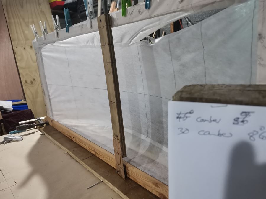
    To examine the distribution of camber across the height of a shelf foot panel and to compare 30 degree shelf with 45 degree shelf in that regard, I made four different panels (1000mm x 400mm) from a fairly stiff, 75gsm nylon cloth. 

    There was no difference between 30 degrees and 45 degrees in the difficulty or otherwise of calculating the width sections of the shelf, if anything 45 degrees was easier. In any case, all arithmetic was done in an instant using an excel spreadsheet. [It is a trivial point, but if there is an "easy one" it would be shelf angle 37 degrees, because you could scale off a 3,4,5 triangle and not need to use trig tables.]

    In addition, two panels were made with the barrel round method, as I was expecting to see some contrast. The barrel round method certainly is much easier and quicker than the shelf foot method.


    The result was: there was little difference between the shapes of any of them, apart from the actual amounts of camber. The shapes across the height of the panel are all somewhat flat on the sides and bottom, with a "soft chine" transition in roughly the same place - even with the barrel round panels, the shapes were suspiciously "tin plate" looking. I was afraid that the type of cloth might have been a problem, perhaps not representing the real life situation, due to problems scaling down in size.

    Second set of tests

    I did the complete experiment all over again, this time making panels from 30 gsm PelTec, an extremely light and soft Tyvec-like material, almost transparent, a bit fiddly to use but hopefully better representing at scale, the typical cloth used in making full size junk sails. There are a few creases and wrinkles – but generally it was easy enough to get the gist of each of the panel shapes.

    The aspect ratio of this relatively wide panel is a bit different from that of the normal narrow junk sail panels and this may have affected the camber shapes. (This p/B ratio of 1000/400 more closely resembles the proportions of the Amiina lower mains panels, which is what I am more familiar with).

    Three panels (30 degree shelf foot, 45 degree shelf foot and barrel-round were made, with a “designed camber” of 8%.  The foil shapes were all mapped from the same identical foil, a simple, relatively sharp entry shape, easy to loft, with max camber at 33.5% of chord.


    (The barrel-round camber was not really “designed” – I just used the same foil above, scaled it to a maximum of 45mm and used it for the “rounding”, hoping this would give a camber of about 8%.)

    Three more panels were made, identical to above, except the designed camber was this time 10%, and I gave the barrel-rounded panel an extra 10 mm of round.

    The panels were inflated and the resulting cambers, as measured, were: for 30 degree shelf: 9% and 10.5%, for 45 degree shelf: 8.6% and 10.5%, and for barrel-round the cambers measured out as: 8.5% and 10%. So, we have two sets of three, with comparable cambers, to compare.

    The panels were inflated with a leaf blower (a little bit too directional, but a strong wind force was necessary) and an attempt was made to measure the camber at various points along the height of the panel, from “lower batten” to “upper batten” along a line through the point of maximum camber.

    Across the 400mm height, the measurement points (which became X-coordinates” were at: 45mm, 90mm, 200mm, 310mm and 355mm.  The measurements of camber at the various points up the height of the panel became the Y- coordinates, and the Y-value at the point “200mm” is in fact the measured maximum camber, mentioned in a previous paragraph.

    In order to compare the distribution of camber (as opposed to the amount of camber) the Y values of all of the data sets were scaled so that the maximum camber was 8.5% (for the first data set of three) and 10% (for the second data set).

    The results were put back into the excel spreadsheet, which produced the following graphs:


    The extreme edges of the panels were too difficult to measure, and the resulting automated “smoothing” of the data is a little odd, so the graphed shapes are slightly different from what the eye could see. The sides of the panels tended to be a little more curved than the flat sides represented here, and where the middle section of a panel rolls into the “soft chine”, those little bumps on some of them are a quirk of the data smoothing algorithm, and may be ignored.

    If these graphs look like round plastic wash basins (inverted) then the 30 degree basins will hold a little more water than the 45 degree basins, because the “bottom” is flatter and the “sides” are very slightly closer to vertical, especially at the very outer edges. This amounts to a slightly better distribution of camber across the height of the panel.

    The basin shape in the 45 degree10% (the 4th diagram) looks rather like a vertical cross section of the panels on my Serendipity (which were made from a very, very soft nylon approx. 70 gsm – cloth taken from an old well-used spinnaker).


    At the extreme outer 3 or 4 cm at the edges, there was no measured data and this distorts the graph a little. In reality the panels tend to be a bit more “horizontal shelf-ish” at the edges than the graphs indicate – as already mentioned. This was more noticeable in the 30 degree shelf and the barrel round panels, and less in the 45 degree panels. The differences were not great, and the middle 80% - 90% of the graphs is a pretty fair representation.

    The thing which surprised me most was how closely the cross section of a barrel-round panel resembles the cross section of a 30 degree shelf angle panel. The outlier here is the 45 degree panel, which does seem to distribute camber in a more shapely but perhaps slightly less efficient manner than the other two, though it seemed to me to be slightly easier to inflate.

    I did observe, while using this very light and flimsy material, that the panels all seemed to be distributing the forces within the cloth in a rather similar and (to me, unexpected) way. The middle cloth of the shelf foot panels seems to be fully tensioned, leaving the shelf cloths to act more as “gap fillers”. Not entirely – but the shelfs seemed a bit less tensioned than the middle. Indeed, one of the shelf foot panels split along a seam from the gale force of the leaf blower (no stitching was used here, only basting tape) - the middle cloth continued to do the job on its own and the panel did not really change shape.


    So, I think the middle cloth is doing a bit more than its share of the work.

    Arne refers to the way a barrel-round panel seems to “rob cloth” from elsewhere in the panel in order to take up a smooth shape – this barrel-round method which “should not work but does work”, seems to do the job in a similar way to the shelf foot panels - the middle part of the barrel-round panel does seem to load up and become quite flat, like the shelf foot panels, leaving the outer edges free to turn in that characteristic “soft chine” shape that all of the panels have.

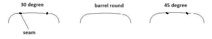
    The “soft chine” or transition between the “sides” of the panels and the slightly curved “bottom” does not coincide with the shelf seam, by the way, as it always appears to do in the photographs. That seems to be an optical illusion. The cloth decides where that soft chine occurs – and indeed puts the soft chine pretty much in the same place regardless of where the seam is, and the same soft chine appears there even in a seamless barrel-round panel.

    It seems as though maybe the panels all "rob cloth"  from the middle in order to take up a fairly universal panel shape, regardless of construction method.


    These were things that I thought was a bit interesting.

    The raw data is available if anyone wants it.


    Last modified: 29 Jan 2024 10:12 | Anonymous member (Administrator)
  • 22 Jan 2024 15:18
    Reply # 13304169 on 13303066

    It was me who was playing with a fudge factor to try and convert the chain calculator into numbers for a spreadsheet. I reckoned it would be useful to be able to put the requirements into a spreadsheet and simply get the answers needed, and that is what I eventually did.

    The ‘Universal round and broadsheet calculator.xls’ in my notes on the website is all that I have ever used since that time, and even though I haven’t really tried to measure or analyse the results in any detail I’ve been happy with the resulting sails. If you make an angled shelf foot main panel it is still necessary to make the centre panel longer than the length along the battens, and the spreadsheet will give a fairly adequate answer to that calculation.


    Last modified: 23 Jan 2024 07:32 | Anonymous member (Administrator)
  • 22 Jan 2024 12:17
    Reply # 13304068 on 13303066
    Anonymous member (Administrator)

    I misunderstood - thanks Slieve for correcting the record.

    (("Fudge factor" is not the correct term for what we are talking about here, I shouldn't have used it. In this case the multiplier is not being used to fudge the data. We don't have a formula which accurately relates Round to Camber - the 20% Arne used is a correction factor which has been found, by experimentation, to correct the output of the chain calculator (which we know does not perfectly simulate the cross section of a cambered sail panel). Fudging is when you alter measured data to make it fit a desired outcome ie cheating. It was the wrong word to use. It's more like a rule of thumb which has been found in practice to work, when we don't necessarily know why. Sometimes it's all you can do. [edit: Slieve's Universal Round and Broadseam calculator is another example of the same thing.])

    Last modified: 27 Jan 2024 00:31 | Anonymous member (Administrator)
  • 22 Jan 2024 10:32
    Reply # 13304065 on 13303066

    Oops!

    Sorry Graeme, but you haven’t explained that diagram and its history correctly, simply because I didn’t give you the whole story. That diagram was a ‘back of an envelope’ sketch which pre-dates the Poppy rig, and which I drew when trying to find a simple mathematical solution to Arne’s chain calculator. I remember hanging a length of chain from door handle to door handle across the kitchen cupboards, and also trying to flatten the curve as Arne suggested. I think I used masking tape to stick on the camber shape I wanted on the doors, and tried to get the chain to take that shape. The chain length was then compared to my calculations, and a ‘fudge factor’ added. This was totally an unacceptable practice as I was taught never to use fudge factors.

    The complication that was clear was that hollow in the luff and leech would effect the shape of the camber as Arne has so rightly mentioned in a recent posting.

    I never considered using a ‘flat’ shelf foot, and only used angle shelf foot on jib panels.

    When Len mentions using round and darts we must remember that ‘darts’ and ‘broadseam’ are effectively the same thing. The problem is that in a stiff sail material the darts cannot be as smoothly blended into the material whereas simply slowly broadening the seam when two cloths are joined gives a smooth subtle curve to the camber. On the Amiina Mk2 rig I made some false broadseams, which were finely tapered cuts (darts) into the edges of the panels and added a patch over the butted edges. It worked very well, but was a slow procedure. Next time I would probably simply slice across the panel and use normal broad seams as once you have done a couple you can quickly ‘eyeball’ the shape as you stick the basting tape down to join the panels, so it only takes a couple of seconds to build the shape into the panel.

    In my eyes round and broadseam (or barrel cut and darts by another name) is by far the easiest and quickest way to make a panel which is tight at both luff and leech. By laying the cloths with the thread line vertical (parallel to the leech) there is minimum wastage in material, and when the cloths are joined the cambered shape is built in.


  • 22 Jan 2024 00:37
    Reply # 13303994 on 13303066
    Anonymous member (Administrator)

    In reply to Arne’s recent interesting post describing how he came to invent his “chain calculator” and its 20% multiplier, I just want to express my admiration again for these pioneers who thought these problems out by themselves and came up with these innovations which we are now discussing, the details of which we are occasionally arguing about. These guys had nothing to start with, and not the same opportunity for discussing with others as we have today.

    The history and the way in which the modern cambered junk sail evolved (and is still evolving) has always interested me. Slieve is another who fits the above category. I got this little gem from Slieve this morning – a diagram scribbled on a scrap of paper which he does not now remember – evidence of the thinking that was going into his brain-child the SJR, and how the shelf foot method relates to camber shape along the height of a panel. Here it is:

    [Analysing the above and reversing the conclusions Slieve expressed: the 45 degree tin plate model predicts amount of camber will be round/.414   and the "soft chine" model predicts amount of camber will be round/0.57.   Both within the range of the much wider set of results arising from Arne's more comprehensive chain calculator tables.

    And there's that basin shape curve yet again...]

     It was done during the Amiina phase, by which time Slieve would have had a pretty good idea of the shape a 45 degree shelf foot panel will take, along the height of a panel. As it happens he dumped the idea and went back to the simpler flat angle shelf as the design model – it's just an interesting little snapshot of the thinking processes that were going on.

    Again, remember, these guys had nothing to copy. Slieve and Arne are not the only ones who innovated and there are others today who are still innovating. As a sideline commentator I can only express admiration, and we are lucky to inherit the results of their original thinking, through their generous sharing and the medium of the JRA. Thanks guys.

    ..............................................................

    Len: Thanks for taking an interest, and your point acknowledged (though not 100% agreed). Perhaps we need another thread for SJR jibs; they still seem  to me to be fundamentally a different animal. PS you may be interested in the barrel-round jibs on Custard's SJR sail which are reported by Martin B as successful in magazine #83, which is probably the answer to David D.'s question. Same design dinghy too. I actually thought Martin and David were already in contact. I wouldn't do it that way - but I don't claim to be an authority.

    Last modified: 22 Jan 2024 09:13 | Anonymous member (Administrator)
  • 22 Jan 2024 00:15
    Reply # 13303982 on 13303965
    Anonymous wrote:

    Sorry Len, the jib panel for a SJR does not attach to the batten, it attaches to a "sheeting angle" cloth. I suggest leaving jibs out of

    You seem to have missed A) what the original poster asked and therefore B) what my answer was actually saying

    the discussion for the present, I think it is a different kettle of fish. In the meantime, the best source for SJR jibs is probably Slieve's notes.

    this is basically what I said. Using the barrel method or dart method to make jiblets, while maybe possible, was more difficult than the original method and not worth while. The sheeting angle and camber are built into the shelf, it should be theoretically possible to achieve the same shape using darts on one piece of cloth instead of three, incorporating the sheeting angle, camber and panel surface. However, as I said, more difficult not easier. I agree Slieve had the right idea.

  • 21 Jan 2024 23:27
    Reply # 13303965 on 13303066
    Anonymous member (Administrator)

    Sorry Len, the jib panel for a SJR does not attach to the batten, it attaches to a "sheeting angle" cloth. I suggest leaving jibs out of the discussion for the present, I think it is a different kettle of fish. In the meantime, the best source for SJR jibs is probably Slieve's notes.

    Last modified: 21 Jan 2024 23:44 | Anonymous member (Administrator)
  • 21 Jan 2024 22:53
    Reply # 13303960 on 13303598

    Arne's method does seem like the easiest to construct, but I don't think it could be made to manufacture jiblets, or could it?

    It could.... but there are good reasons not to. Arne relates two methods of achieving camber, barrel and darts. The barrel shape needed for jiblets would require much more wrinkles along the battens, maybe enough to cause fatigue in the fabric from folding, thus wearing holes. The dart version would probably require making a shelf pattern first and then cutting slits in it till the curved side was straight (assuming a 90degree shelf). Then using that as part of the panel pattern (one top and one bottom). I think that with the need create a shelf panel anyway, all the hard work is already done and the sewing part may actually be easier with the shelf method than the dart method.

    If there is an easier method, it would be the "Origami" method. See the JRA magazine issue 84 and 85.

  • 21 Jan 2024 15:50
    Reply # 13303846 on 13303066
    Anonymous member (Administrator)

    Actually, while trying to make a simple way of calculating camber (1999), that ‘fudge factor’ in the Chain Calculator write-up was not taken from thin air.

    What happened in 1993 was that I made a full-size test panel (see NL #30 p.22) before daring to make the first cambered panel JR for Malena. I aimed for 10% camber, but it ended up at only about 8%. Still, I decided that this was good enough, so Malena’s sail was made with this 20cm Round along the upper and lower edge of the panels.
    The sail turned out to work very well.
    Then in 1999, prior to designing a rig for my next boat, Johanna, I made use of the data from the test panel to establish the chain calculator.

    When hanging a chain on two nails, 0.95m apart (i.e. at batten distance) and letting the chain length be the same as the max. width of the test panel (here 1.35m), I found that the maximum chain camber came out at about 440-450mm, or 20% deeper than the actual sail camber.
    That’s how I settled on this fudge factor of 1.20. No advanced maths involved and not super accurate, but plenty good enough.

    Note: The chain Round is not increased with 20%, only the resulting chain camber. It only takes a few % longer chain to achieve 20% more chain camber.
    See Chapter 4, p. 8 to see how the chain (‘catenary’) curves look like.

    Curve (real camber) from luff to leech:
    I know, I know, I am kind of cheating by trying to make a fully 3-dimansional shape out of a flat sheet of cloth. However, it has turned out to work. The fact, which only recently dawned to me, is that the success of the barrel-only method does not depend on stretchy cloth. The extra 2-4cm needed to take up that (camber) curve along the middle of the panel, has simply been stolen from the luff or leech of each panel. This results in a bit hollow in the (luff and) leech of each panel, as on the photo below. My guess is that this is the reason why the panels don’t end up with a hooked leech, despite the use of a boltrope.

    Arne


    Last modified: 22 Jan 2024 10:16 | Anonymous member (Administrator)
<< First  < Prev   1   2   Next >  Last >> 
       " ...there is nothing - absolutely nothing - half so much worth doing as simply messing about in junk-rigged boats" 
                                                               - the Chinese Water Rat

                                                              Site contents © the Junk Rig Association and/or individual authors

Powered by Wild Apricot Membership Software