Distribution of moment and strength
Now I have tried to sort out my thoughts about the distribution of bending moment on a free-standing, wooden JR mast.
‘Case JR’ has to sit somewhere between these two extremes:
Case 1) The sail is only working at one point; the mast top.
Case 2) The sail distributes the pressure perfectly evenly, up along the mast.
On Fig. 1, the resulting moment curves along a mast have been drawn up. Case 1 results in a curve which is a straight line, while Case 2 results in a parable curve.
Then I have calculated the strength distribution of a PJR-style cone-tapered mast, and then superimposed it onto the same diagram. As can be seen, such a mast would have proven to be fine if the JR lived in a perfect Case 2 situation. However, practical experience has shown that such masts tend to bend quite a lot around their middle, so I suspect that Case 1 is a better and safer model for designing a mast for JR.
On Fig. 2, I have removed the Case 2 curve, but have introduced two more masts, and calculated their strength curves. The barrel-tapered mast, nicked from “Skene’s Elements of Yacht Design”, fits in very well with the Case 1 load distribution. However, it will be a challenge for an amateur to build. I have therefore suggested a modified cone-tapered mast, which keeps full diameter up to 20% above partners, and then tapers to 45% thickness at the mast top. This will also have a good strength distribution, and will be much easier to build, although a bit heavier than Skene's mast.
I would anyway stay away from the PJR-style mast, from now on, in particular since my Johanna-style sails put some loads 'up there'.
Figure 3 shows the actual distribution of diameters of the three masts.
Fig 1

Fig 2
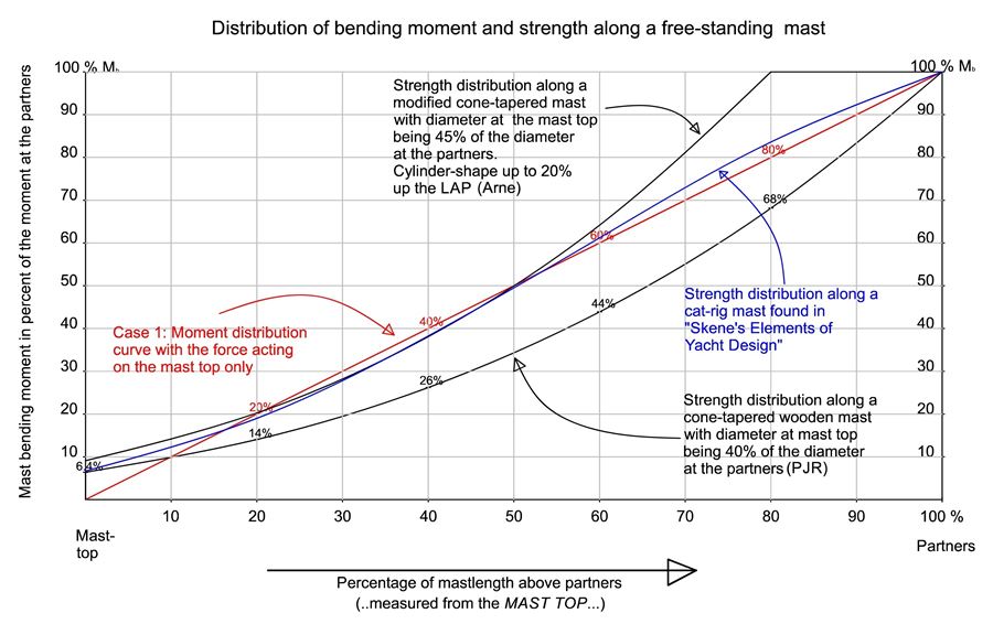
Fig 3

(full size diagrams at Arne's Sketches, section 3, photo 36-38)